Motor Structure Design
- Sinovation-EV
- 2021年11月24日
- 讀畢需時 3 分鐘
According to GB1471l-2013 "General Safety Requirements for Small and Medium-sized Rotating Electric Machines", GB 755-2008 "Performance of Rotating Electric Motors", GB/T 18488.1-2015 "Technical Conditions of Drive Motor Systems for Electric Vehicles Part 1", GB/T 18488.2- 2015 "Drive Motor System for Electric Vehicles Part 2: Test Methods" and other standards regarding the requirements of the operating environment and electrical safety, the high-voltage safety of the motor is the design focus of the electric drive system of electric vehicles. The structure of the motor is mainly designed from the aspects of waterproof, flame-retardant, and anti-corona functions.
1) Waterproof
2) Flame retardant
3) Anti-corona
4) Motor controller

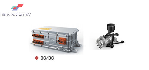
The motor controller modulates the output sine wave through the inverter bridge to drive the motor, which can be divided into a single controller and an integrated controller. Pure electric vehicles using a single controller also require independent high-voltage power distribution cabinets, DCDC converters and other high-voltage components. There are many high-voltage connection points, heavy weight, and occupy a lot of layout space. The integrated controller has various integration forms, such as three-in-one controller (EHPS controller + motor controller + DC / DC converter integration), five-in-one controller (EHPS controller + motor controller + DC / DC conversion Controller + high voltage power distribution + air compressor controller integration), passenger car controller (motor controller + DC / DC converter integration), etc. The integrated controller is light in weight, small in size, few high-voltage connection points, and high in protection level, and is widely used in pure electric vehicles. The all-in-one integrated controller includes power distribution circuit, IGBT drive circuit, DSP circuit, structure and heat dissipation system, etc.
The actual operating environment of the whole vehicle is complex and the working conditions are relatively harsh, which puts forward high requirements on the thermal design of the integrated controller. It is necessary to carry out device-level and system-level thermal simulations, to simulate and test the thermal field models under different working conditions of the integrated controller modules, and to optimize the design of high-efficiency heat exchange cooling fluid channels.

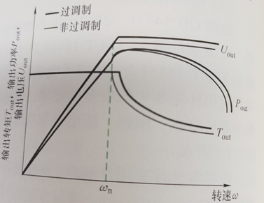
In addition, in order to optimize the efficiency of the electronic control system, it can be optimized through dynamic distortion adjustment, DDWM wave technology, and over-modulation technology. The dynamic adjustment of the carrier frequency can select the carrier frequency reasonably according to the working conditions, which can effectively reduce the loss of the controller and improve the efficiency of the controller: DPWM wave generation technology can effectively reduce switching loss: Overmodulation technology can increase the fundamental voltage and reduce the motor current. Improve the highest efficiency of the motor and broaden the range of the high-efficiency area.

5) Motor suspension design.
The power system is the most important excitation source of vehicle vibration and noise, which reduces the vibration transmitted from the power system to the vehicle body. Generally, Figure 3-5 over-modulation effect
Set up a suspension question between the body and the power system. Suspension system points
There are two categories of suspension brackets and suspension cushions: suspension brackets refer to the parts that connect the motor and the suspension and between the frame and the suspension; the suspension cushions refer to the connection between the upper and lower suspensions. Elastic element device. The function of the suspension is to realize the force and moment transmission between the powertrain and the plus, and to transfer the motor to the support system or to minimize the vibration of the support system to the motor.
6) Drive shaft design
The speed and torque transmission between the motor and the rear axle is mainly connected by the drive shaft. The output end of the direct drive motor generally reserves a flange mounting surface to facilitate the installation of the drive shaft.
Comments